


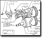
70 Class Machines Frame Cap Assembly and Main Cam Shaft
FRAMECAP ASSEMBLY
 |
1) To remove the Frame Cap Assembly, remove the Dust Shield, Needle Plate, and the Upper and Lower Loopers. Remove the four Screws 99-3/16 in the Frame Cap and turn the Hand Wheel until both Looper Carrier Assemblies are at the extreme right-hand position. Then, the Frame Cap Assembly may be readily pulled toward the operator and removed from the machine. To re-assemble, place each Cam Roll on the Upper Looper Carrier and oil them. Turn the Hand Wheel while observing the groove in the Lower Cam, and stop the Lower Cam when the observed portion of this groove is farthest to the right. The Frame Cap Assembly may then be put into position as it was removed.
UPPER AND LOWER LOOPER CARRIER ASSEMBLY
2) The Upper Looper Carrier Assembly is pivoted on the Lower Looper Carrier Assembly. The Upper and Lower Looper Carrier Assemblies must be perfectly free to travel their full stroke along the Upper Looper Carrier Slide Rod, but must have little lost motion. The Upper Looper Carrier Guide serves to limit the sidewise motion of the Looper Carriers during their back and forth stroke. The Upper Looper Carrier Guide Shim M-269-1 (round) (2) and Upper Looper Carrier Guide Shim M-269-11 (square) are provided under the points of support of this Upper Looper Carier Guide. All of these Shims are marked with a number which designates its thickness in inches. Thicker or thinner shims of either type may be purchased in graduated steps of one-half a thousandth of an inch. When adjusting the Upper Looper Carrier Guide, suitable Shims should be provided under each end of it so that when the Guide is securely fastened in place, there will be a uniform opening between this Guide and the Upper Looper Carrier of slightly less than one thousandth of an inch.
3) The above mentioned adjustment of the Upper Looper Carrier Guide is made at the factory and most machines run four or five years without readjustment unless there is an accident spoiling one of the parts. Whenever any of the parts compiling this assembly are replaced, this adjustment should be checked.
4) The Cam Rolls for the Upper Looper Carrier Assembly are identical. If excessive up and down looseness of the Loopers develops, these Cam Rolls may need replacing which is simply accomplished by removal of the Frame Cap Assembly.
TO REMOVE THE UPPER AND LOWER SHAFTS AND CAMS
In order to remove the Main Shafts, proceed as follows:
 |
NOTE: It is unnecessary to drain the oil from the machine.
- After swinging the Presser Foot Assembly out of the way for accessibility, remove the Needle Plate and Lower Looper Thread Tube from the Machine.
- Remove the Frame Eccentric Nut 2-3/16 and the Feed Carrier Link “r” Nut 2-3/16. Then remove the Feed Carrier Link “r” and the Feed Eccentrics.
- To remove the Work Plate Support take out the two Screws 52-3/16 which hold the Work Plate Support to the Frame.
- Slide the Feed Carriers from the F.R. Eccentric Block and the Feed Carrier Block and remove the Blocks.
- Remove the Needle Carrier Stud after loosening the Set Screw 8-7/32. Slide the Needle Carrier Assembly and the Needle Carrier Link Assembly from the machine.
- Remove the Frame Cap Assembly as described previously.
- To remove the Upper Shaft Assembly and Upper Cam, proceed as follows:
- Remove the Upper Shaft Pump Parts (Screw 8-7/16, Spring 27-40, and Oil Pump Plunger). Care must be taken not to harm the Oil Pump Plunger Screw Gasket.
- Loosen Screw 5-9/32 and remove Frame Cap Oil Feeder Tube Assembly, M-95-Assy.-4. Note: When replacing this part, point projection on this tube downward.
- Remove Screw 2-1/2, now insert a 7/32 Screw several turns into the U.S. Oil Meter Holder M-137-5. Pull this part up and out of the machine. Note: When replacing Upper Shaft Oil Holder M-137-5, place pointed projection on this part into the hole in Upper Shaft Oil Collector M-137-3.
- Insert a 1/8 Screw several turns into the Upper Shaft Oil Collector M-137-3 and remove from the machine.
NOTE: When replacing Upper Shaft Oil Collector M-137-3, place into the machine with the hole in the large end pointing upward.
- Loosen the Socket Screw 32-1/4 in the Upper Cam.
- Pull the Upper Shaft Assembly out until the end of the eccentric cut on the Upper Shaft strikes Upper Cutter Carrier Eccentric Block (about 1/2 inch) (12 mm). While exerting pressure to pull the Upper Shaft Assembly further out, move the Upper Cutter Carrier Assembly up and down. This action will allow removal of the Upper Shaft Assembly and the Upper Cam.
NOTE: If it is necessary to use a rod to loosen the Upper Shaft Assembly from its bearings, use a soft rod of between 1/4" (6.5 mm) and 3/8" (9.5 mm) diameter.
A.To remove the Lower Shaft and Lower Cam, proceed as follows: 1. Loosen the Socket Screw 32-1/4 in the Lower Cam. 2. Grasp the Hand Wheel and remove the Lower Shaft and Lower Cam. A.The Lower Shaft Oil Meter and Lower Shaft Oil Meter Holder 6-9/32 removed by first taking out Plug Screw A-288-3 from bottom of machine. Lower Shaft Oil Meter Holder 6-9/32 may now be removed with a screw driver from its location between the Shafts. B.Before re-assembling, clean all parts including the oil holes and slots in the Frame. C. In re-assembling, the gears on the two Main Cams are meshed correctly by: 1. Removing the Cam Timing Screw 3-#8 located in the Frame in back of the Dust Shield. 2. Placing Screw in the Lower Cam and matching the Screw with the hole in the Upper Cam. 3. Removing Screw 3-#8 from Cam and replacing in storage hole in Frame. The machine will not make a full revolution when this Screw is in the Cam and the Frame Cap is assembled into machine. - Remove the Upper Shaft Pump Parts (Screw 8-7/16, Spring 27-40, and Oil Pump Plunger). Care must be taken not to harm the Oil Pump Plunger Screw Gasket.