


70 Class Machines Loopers
1) The Upper and Lower Looper must cooperate with the Needle in order for sewing to occur. Before making any Looper adjustments always change to a new Needle. A new Needle may solve your problem without further adjustments.
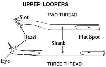
2) The Upper Loopers are made in two general forms, one for two-thread stitching and the other for three-thread stitching. Adjustment of both forms are the same.
3) The Loopers are nearly self-setting, but they may need slight bending to achieve proper setting. Always bend Loopers slightly farther than the position you desire. The Loopers have a tendency to spring back to their original (pre-bent) position, if you don’t bend them far enough. Loopers are designed to be bent only in the shank area. The point areas are hardened to prevent wear and do not take a bend well.
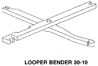
4) To bend the Loopers, we recommend Merrow Looper Bender 30-10. Some people use the shank of a screwdriver, or pliers to do the bending. Please note: If pliers are used, they must be smooth surfaced to prevent damage to the surface of the Loopers. A good light is recommended for visibility when setting the Loopers. A piece of white paper placed behind the Loopers also makes them more visible.
LOOPER SETTING
5) The following instructions are designed to give you a general knowledge of Looper setting. You should be able to make any Merrow class 70 machine sew after following these instructions. Specific styles will require further "fine tuning" to get the ideal setting. Talk to your local Merrow sales representative for tips on setting your specific style of machine.
- Move the Presser Foot Assembly out of the way, and remove the Needle Plate, Lower Looper Thread Tube, Feed Dogs, and Dust Shield for accessibility. Loosen set screws 2-#3 or 1-#8 and remove Loopers.
- Insert Lower Looper into the Lower Looper Carrier. Push it into the carrier until you feel it stop against the pin. Tighten the set screw 2-#8 against the flat spot on the shank of the looper. Note: Before inserting the Looper make sure the hold in the Looper Carrier and the area around it are clean. If you push dirt into the hole the Looper will stick out too far and become hard to adjust properly. If this has happened, remove the Frame Cap and clean out the Looper Carriers from the opposite end with a wire or pipe cleaner.
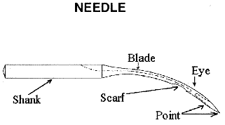
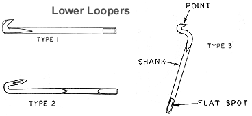
- Turn the Hand Wheel so that the Needle is at its furthest downward position and the Lower Looper is fully extended to the left in its outward motion (see diagram 1). The distance between the point of the lower looper and the Needle should be the thickness of the hook end of your Merrow tweezers 37-225-C. or about 1/32" of an inch (.031). “Type #3 only.” Refer to (diagram A) for bending the Lower Looper to this setting.
- The top corner of the needle point (where the needle meets the blade) should contact the Needle Guard with a little pressure (see diagram 2). To gage this, turn the Hand Wheel to separate the Needle from the Lower Looper. Insert a small scrap of note-paper (this is approximately 3 thousandths of an inch thick) between the Needle and Lower Looper. Turn the Hand Wheel back so that just the thickness of the paper is caught between the Needle and the Looper. You should be able to remove the paper, but you should feel a slight drag against it as you pull it out. Refer to (diagram G) for adjusting Lower Looper type #3 to this setting and (diagram B) for #1 and #2 Loopers.
- Turn the Hand Wheel slightly until the point of the Lower Looper arrives behind the Needle. The point of the Lower Looper should contact the rear surface of the Needle, but it should not deflect the Needle (see diagram 3). The note-paper gage used above also works here. If you are using a "scarfed" Needle, the point of the Lower Looper should still contact, but not deflect the Needle. Generally, a Lower Looper is set tighter to a "scarfed" Needle than a standard Needle. Refer to (diagram B) to adjust the point of the Lower Looper Type #1 and Type #2 to the Needle and (diagram H) for #1 and #3 type Loopers.
- Insert Upper Looper into the Upper Looper Carrier as far as it will go. Tighten set screw (1#8) against the flat spot on the shank of the Looper.
- Gently turn the Hand Wheel over. The Upper Looper if correctly inserted in the carrier will allow the Needle to pass just behind the head. It should also be far enough forward so that its point passes directly behind the head of the type #1 and type #3 lower loopers; or through the scarf, just behind the eye of the type #2 Lower Looper. Look for interference (contact) between the Upper Looper and Needle, or the Upper Looper and Lower Looper. The Upper Looper should NOT contact either the Needle or the Lower Looper. If there is contact, adjust the Upper Looper to clear the one it is contacting. If it is contacting both, adjust the Upper Looper to clear the one it is contacting with the most interference first.
- To adjust the clearance of the Upper Looper refer to bending (diagrams C and D). Moving the Upper Looper from path 1 to path 2 or 1 to 3 (diagram 4) will increase or decrease the clearance between the Upper Looper and the Needle. It will also do the opposite to the clearance between the Upper Looper and Lower Looper. For example, if moving from path 1 to path 3 increases your clearance between the Upper and Lower Looper, it will also decrease your clearance between the Upper Looper and the Needle.
- Adjusting the Upper Looper (diagram 4) along path 1 through the points a,b,c,d, and e will change the clearance between the Upper Looper and the Needle (bending diagram C). Raising and lowering the Upper Looper affects the clearance by changing the timing of the meeting of the Upper Looper and the Needle. Adjusting the Upper Looper along this path will also change the meeting place of the point of the Upper Looper and the rear of the Lower Looper. The point of the Upper Looper should come up behind the head of type #1 and #2, and fall in the scarf of Lower Looper type #3 right behind the eye (see diagram 5 and 6). The point of the Upper Looper should not contact the Lower Looper. To determine if there is contact, place the tip of your left index finger on the exposed shank of the Lower Looper. Turn the Hand Wheel over slowly while holding your finger on the Lower Looper, if there is contact you will feel it. Adjust and recheck until the contact disappears.
- At this point your Loopers should be reasonably set and working with each other and the Needle. Two more adjustments can be made, but they are generally not necessary. (Diagram 8) shows the angle of the Lower Looper, this is pre-set at 3-1/2 degrees. Following bending (diagram F), you can increase or decrease this angle to affect the clearance between the point of the Upper Looper (bending diagram E). This maintains the clearance between the Needle and the Upper Looper, while bringing the point of the Upper Looper closer to or farther away from the Lower Looper.
- When setting two-thread machines 70-2D- or M-2D- or 70-D3B-3 follow the above steps. If the Upper Looper is blind (no eye) set it as high as possible making sure the point still clears the eye of the Lower Looper. This presents a wider loop of thread for the Needle to penetrate. It is more common to follow head rotation (diagram E) when setting the Upper Looper for two-thread style machines.
- Single-thread machines have a blind Lower Looper. These are set the same as an eyed Lower Looper, except rotating the point to the Needle requires the use of diagram I instead of E. Diagrams A, B, and F can still be used.